
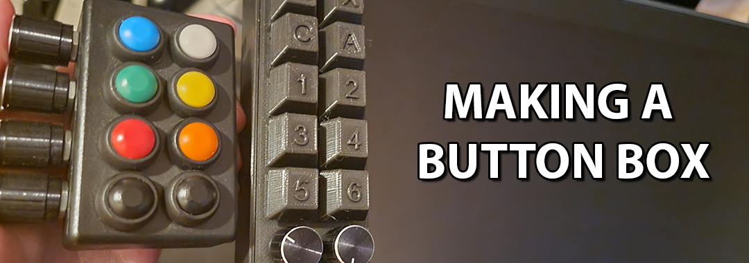
A while back I was looking into various options for a macro pad or companion device for when using my Huion drawing tablet and most solutions seemed rather expensive or just not quite the form factor or tactile functionality I was looking for.
This “button box” has a bunch of buttons and a few dials for zooming and changing the brush size and such. This post is going to cover my current journey up until this point. I’m now on my second revision because I wasn’t satisfied with my initial result. I’ll cover my first revision, button box version one and explain the limitations and then move on to my current version which is touted button box version 2. Yeah the names aren’t great. I need to come up with a better name but for now let’s get right into it!
Not one but two?
So why are you making this and why are you on revision two and thinking of even another 3rd and final version? Well, firstly, let’s look at the form factor for both of these. Button Box V1 (BB1) was an effort resulting from sourcing readily available supplies. The housing was a project box bought off of Amazon, the buttons and dials as well. Heck, everything was bought off of Amazon. Here’s the supply list.
- Buttons
- Rotary Encoders
- Project Box (any box will do)
- 22 Gauge Wire Solid Core Hookup Wire
- Arduino Pro Micro ATmega32U4
- Soldering Iron
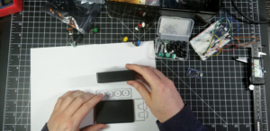
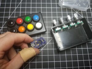
When I started this project I didn’t have a 3D printer but I ended up buying an Ender 3v2 for Button Box V2 (BB2) though. Here’s a pic of the two boxes next to each other:
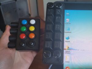
The buttons on BB1 were okay for thumb pressing and required more force to press. It worked well mounted on the edge of my desk. But having one hand reaching over to the desk while drawing on the tablet seemed a little unintuitive. I wanted to have it right on the tablet and have the buttons be Cherry MX switches which are easier to press and much more clickier. And that’s why I made BB2 which is now mounted on the tablet instead of the desk. BB1 actually might still be adequate and just fine for most people so I’ll cover the process of how I made it as well.
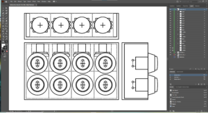
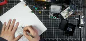
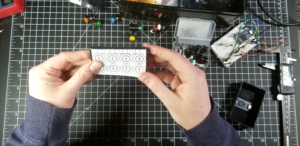
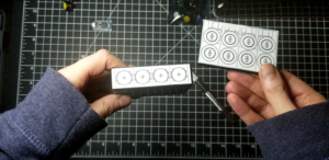
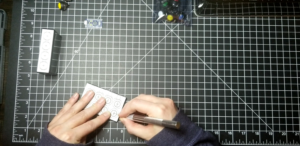
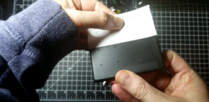
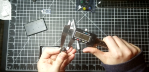
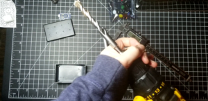
Measurements, Illustrator and Drilling holes
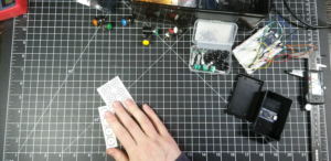
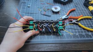
The first step was determining how many buttons/dials I can fit on this project box housing. So I break out the calipers and start taking measurements. I use the measurements and draw up the layout in Illustrator, print it out and then tape it to the box. I then take a blade and score the spots where I’ll be drilling the holes. Now all this might be little overkill. You could easily just eyeball all of this and wing it. But I decided to be more precise to make sure I could fit all the buttons and dials in such a small enclosure.


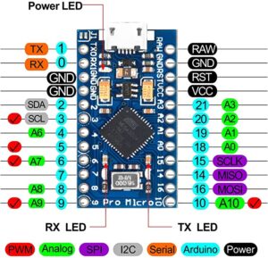
Choosing an IO board and wiring
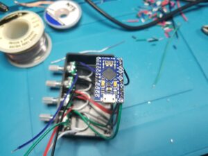
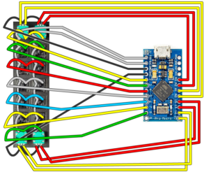
By now I knew how many inputs I needed and they’re all digital. No analog. 8 push buttons, 4 rotary encoders/dials and each encoder has push button functionality so technically that makes a total of 12 push buttons. So I went with the Arduino Leonardo in small form factor which is the ATmega32U4 pro micro. It has plenty of digital pins and can emulate a keyboard and mouse. Perfect. Here’s the pin layout:
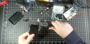
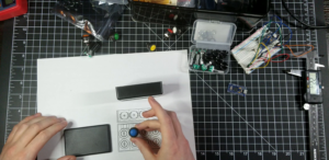
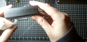
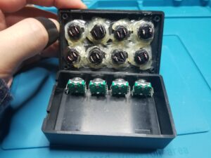
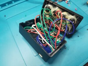
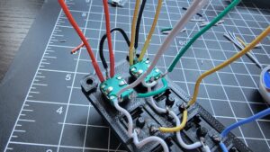
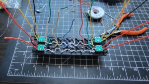
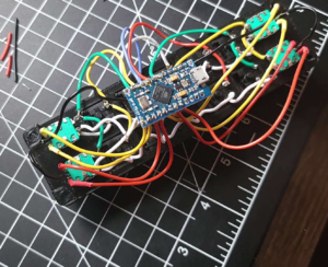
Here it is with all the buttons in place and hot-glued (hot-glue probably unnecessary) but I’m excessive and wanted to ensure the buttons don’t come loose.
Eventually though somehow the connector broke away from the board (probably my fault) but I got some usage out of the BB1 while it lasted…RIP BB1.
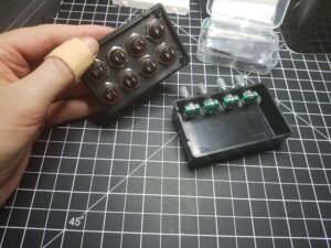
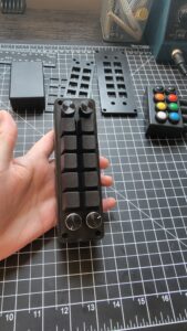
Designing a better box…BB2!
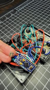
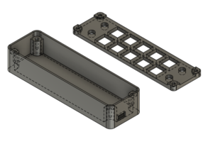
The final product of BB1 is pretty decent and compact. It optimizes all the space for that particular project box. But before we get into the coding, let’s take the design idea further and change the buttons to Cherry MX switches and completely change the layout. Since we have a 3D printer now we’re no longer constrained by the dimensions of a standard project box. We can design our own enclosure in Fusion 360 and print it out!
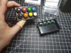
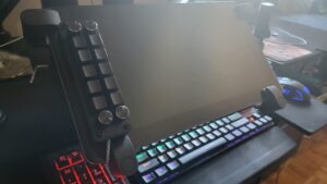
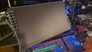
Mounting it on a tablet
Mounting it on a tablet is as easy as using some 3M two-sided tape or I used these Damage Free Command Hanging Strips which I find really keep it secure.
Programming the Arduino
Here’s a simple version of the Arduino sketch that just assigns a character to each button press and dial turn. This isn’t the final version, the final version is a bit more involved and has the ability to set key assignments dynamically rather than just hardcoded. But here’s the simple version to get an idea on how it all works:
#include <Key.h>
#include <Keyboard.h>
#include <Mouse.h>
#include <Keypad.h>


//DEFINITIONS
#define ENABLE_PULLUPS
#define NUMROTARIES 4 //replace "?" with number of rotary encoders you are using
#define NUMBUTTONS 14 //replace "?"with number of buttons you are using
#define NUMROWS 7 //replace "?" with number of rows you have
#define NUMCOLS 2 //replace "?" with number of columns you have

#define CW 0
#define CCW 1
#define PRESS 3

//push buttons
#define BTN_KEY1 '1'
#define BTN_KEY2 '2'
#define BTN_KEY3 '3'
#define BTN_KEY4 '4'
#define BTN_KEY5 '5'
#define BTN_KEY6 '6'
#define BTN_KEY7 '7'
#define BTN_KEY8 '8'
#define BTN_KEY9 '9'
#define BTN_KEY10 'a'

#define BTN_DIAL1 'b'
#define BTN_DIAL2 'c'
#define BTN_DIAL3 'd'
#define BTN_DIAL4 'e'

//rotary encoders rotation
#define DIAL1_CCW 'y'
#define DIAL1_CW 'z'
#define DIAL2_CCW 'w'
#define DIAL2_CW 'x'
#define DIAL3_CCW 'u'
#define DIAL3_CW 'v'
#define DIAL4_CCW 's'
#define DIAL4_CW 't'

//BUTTON MATRIX
//first change number of rows and columns to match your button matrix,
//then replace all "?" with numbers (starting from 0)
char buttons[NUMROWS][NUMCOLS] = {
	  { BTN_DIAL1, BTN_DIAL2 },
	  { BTN_KEY1, BTN_KEY6 },
	  { BTN_KEY2, BTN_KEY7 },
	  { BTN_KEY3, BTN_KEY8 },
	  { BTN_KEY4, BTN_KEY9 },
	  { BTN_KEY5, BTN_KEY10 },
	  { BTN_DIAL3, BTN_DIAL4 }
};

//BUTTON MATRIX PART 2
byte colPins[NUMCOLS] = { 0 , 1 }; //change "?" to the pins the rows of your button matrix are connected to
byte rowPins[NUMROWS] = { 8 , 7 , 6 , 5 , 4, 3, 2 }; //change "?" to the pins the rows of your button matrix are connected to

Keypad kpd = Keypad(makeKeymap(buttons), rowPins, colPins, NUMROWS, NUMCOLS);

struct rotariesdef {
	byte pin1;
	byte pin2;
	int ccwchar;
	int cwchar;
	volatile unsigned char state;
};

//ROTARY ENCODERS
rotariesdef rotaries[NUMROTARIES]{
  {16, 10, DIAL1_CCW, DIAL1_CW,0}, //dial 1
  {15, 14, DIAL2_CCW, DIAL2_CW,0}, //dial 2
  {18, 19, DIAL3_CCW, DIAL3_CW,0}, //dial 3
  {20, 21, DIAL4_CCW, DIAL4_CW,0} //dial 4
};

#define DIR_CCW 0x10
#define DIR_CW 0x20
#define R_START 0x0

#ifdef HALF_STEP
#define R_CCW_BEGIN 0x1
#define R_CW_BEGIN 0x2
#define R_START_M 0x3
#define R_CW_BEGIN_M 0x4
#define R_CCW_BEGIN_M 0x5
const unsigned char ttable[6][4] = {
	// R_START (00)
	{R_START_M,            R_CW_BEGIN,     R_CCW_BEGIN,  R_START},
	// R_CCW_BEGIN
	{R_START_M | DIR_CCW, R_START,        R_CCW_BEGIN,  R_START},
	// R_CW_BEGIN
	{R_START_M | DIR_CW,  R_CW_BEGIN,     R_START,      R_START},
	// R_START_M (11)
	{R_START_M,            R_CCW_BEGIN_M,  R_CW_BEGIN_M, R_START},
	// R_CW_BEGIN_M
	{R_START_M,            R_START_M,      R_CW_BEGIN_M, R_START | DIR_CW},
	// R_CCW_BEGIN_M
	{R_START_M,            R_CCW_BEGIN_M,  R_START_M,    R_START | DIR_CCW},
};
#else
#define R_CW_FINAL 0x1
#define R_CW_BEGIN 0x2
#define R_CW_NEXT 0x3
#define R_CCW_BEGIN 0x4
#define R_CCW_FINAL 0x5
#define R_CCW_NEXT 0x6

const unsigned char ttable[7][4] = {
	// R_START
	{R_START,    R_CW_BEGIN,  R_CCW_BEGIN, R_START},
	// R_CW_FINAL
	{R_CW_NEXT,  R_START,     R_CW_FINAL,  R_START | DIR_CW},
	// R_CW_BEGIN
	{R_CW_NEXT,  R_CW_BEGIN,  R_START,     R_START},
	// R_CW_NEXT
	{R_CW_NEXT,  R_CW_BEGIN,  R_CW_FINAL,  R_START},
	// R_CCW_BEGIN
	{R_CCW_NEXT, R_START,     R_CCW_BEGIN, R_START},
	// R_CCW_FINAL
	{R_CCW_NEXT, R_CCW_FINAL, R_START,     R_START | DIR_CCW},
	// R_CCW_NEXT
	{R_CCW_NEXT, R_CCW_FINAL, R_CCW_BEGIN, R_START},
};
#endif

// the setup function runs once when you press reset or power the board
void setup() {
	rotary_init();
	Keyboard.begin();
	Serial.begin(9600);
}

// the loop function runs over and over again until power down or reset
void loop() {
	CheckAllEncoders();
	CheckAllButtons();
}

void rotary_init() {
	for (int i = 0; i < NUMROTARIES; i++) {
		pinMode(rotaries[i].pin1, INPUT);
		pinMode(rotaries[i].pin2, INPUT);

#ifdef ENABLE_PULLUPS
		digitalWrite(rotaries[i].pin1, HIGH);
		digitalWrite(rotaries[i].pin2, HIGH);
#endif
	}
}

unsigned char rotary_process(int _i) {
	//Serial.print("Processing rotary: ");
	//Serial.println(_i);
	unsigned char pinstate = (digitalRead(rotaries[_i].pin2) << 1) | digitalRead(rotaries[_i].pin1);
	rotaries[_i].state = ttable[rotaries[_i].state & 0xf][pinstate];
	return (rotaries[_i].state & 0x30);
}

void CheckAllEncoders(void) {
	//Serial.println("Checking rotaries");
	for (int i = 0; i < NUMROTARIES; i++) {
		unsigned char result = rotary_process(i);
		if (result == DIR_CW) {

			Keyboard.press(rotaries[i].cwchar);
			delay(50);
			Keyboard.release(rotaries[i].cwchar);

		};
		if (result == DIR_CCW) {
			Keyboard.press(rotaries[i].ccwchar);
			delay(50);
			Keyboard.release(rotaries[i].ccwchar);
		};
	}
	//Serial.println("Done checking");
}

void CheckAllButtons(void) {
	if (kpd.getKeys())
	{
		for (int i = 0; i < LIST_MAX; i++)
		{
			if (kpd.key[i].stateChanged)
			{

				switch (kpd.key[i].kstate) {
				case PRESSED:
					Keyboard.press(kpd.key[i].kchar);
					//Joystick.setButton(kpd.key[i].kchar, 1);
					break;
				case HOLD:
					//Joystick.setButton(kpd.key[i].kchar, 1);
					break;
				case RELEASED:
					Keyboard.release(kpd.key[i].kchar);
				case IDLE:
					//Joystick.setButton(kpd.key[i].kchar, 0);
					//Keyboard.release(kpd.key[i].kchar);
					break;
				}
			}
		}
	}
}
Later on I added more functionality by monitoring the serial port for incoming commands. Just added it to the main loop and checked for any incoming strings. Using a “:” delimiter you can split/explode the string into various strings and check each of those strings for commands. A command string would look something like this “SETKEY:1:Copy:c:0:0:1:0:0:1”
void loop() {
	// check if data is available
	if (Serial.available() > 0) {
		// read the incoming string:
		String incomingString = Serial.readStringUntil('\n'); //Serial.readString();


		ind1 = incomingString.indexOf(':');
		sCommand = incomingString.substring(0, ind1);
		ind2 = incomingString.indexOf(':', ind1+1);
		sKey = incomingString.substring(ind1+1, ind2);


		if (sCommand.equals("SETKEY") || sCommand.equals("SETKEYLP")) {
			ind3 = incomingString.indexOf(':', ind2 + 1);
			sName = incomingString.substring(ind2 + 1, ind3);
			ind4 = incomingString.indexOf(':', ind3 + 1);
			sChar = incomingString.substring(ind3 + 1, ind4);
			ind5 = incomingString.indexOf(':', ind4 + 1);
			sWheelUp = incomingString.substring(ind4 + 1, ind5);
			ind6 = incomingString.indexOf(':', ind5 + 1);
			sWheelDown = incomingString.substring(ind5 + 1, ind6);
			ind7 = incomingString.indexOf(':', ind6 + 1);
			sCtrl = incomingString.substring(ind6 + 1, ind7);
			ind8 = incomingString.indexOf(':', ind7 + 1);
			sAlt = incomingString.substring(ind7 + 1, ind8);
			ind9 = incomingString.indexOf(':', ind8 + 1);
			sShift = incomingString.substring(ind8 + 1, ind9);
			ind10 = incomingString.indexOf(':', ind9 + 1);
			sVerbose = incomingString.substring(ind9 + 1, ind10);

...
Serial Monitor Companion Program
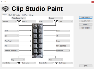
I’ve written a companion serial monitor program for Windows that runs in the background/SysTray. It allows you to customize the buttons and dials functionality by sending a null-terminated string as described above. The windows program also monitors the serial port for strings and shows a popup for each tool/button when activated (if verbose==true). Here’s a short demo video of Button Box V2 in action and how it all works together:
What’s next?
If I were to make a third version. Third time’s a charm right? I’d probably want to have a PCB design and make it even smaller profile. Plus making duplicates for anybody that wants one would be easier and you could even just assemble it yourself. Speaking of which, contact me if you’re interesting in owning one of these and what you plan to use it for. Maybe you’d like to use it with a video editor or maybe even for gaming. Either way it’s a pretty versatile form factor and fully customizable using the companion program.
That’s all, take care!